Engine Cycles
The term “cycles” refers to one complete sequence of operation required to produce power in an engine.
This cycle of operation is continually repeated while the engine is running.
For a diesel engine it consists of for operations within the cylinder.
1. Compression of charge of air.
2. Injection of fuel which then ignites.
3. Expansion of the hot gases formed during combustion.
4. Expansion of the used gas to exhaust.
The cylinder is then recharge with air and cycle is operated.
Diesel engines can be designed to complete this cycle once during each revolution and this is the two stroke cycle or lternately, or alternatively two engine revolution to complete. “the four stroke cycle”
An engine can only operate on the cycle for which it was designed.
Engine Stroke - is measured as the full distance through which the piston moves TDC – BDC.
Engine Timing - Refers to the relative time or position of the crank at which operation during the cycle is commenced and completed. It is measured as the angle through which the crank has been rotated from a datum
position such and top a bottom centre.
Practically all large slow speed direct drive marine diesel engines operate on the two stroke cycle.
A two stroke cycle has take place in two consecutive strokes of the engine piston or one revolution of the crank shaft.
Thus each operation is the cycle is repeated during every revolution of the engine.
The two strokes of the cycle may be termed compression stroke and power stroke or expansion stroke.
Operation takes place in a fixed order and must occur when the piston reaches a corresponding position is its stroke.
These positions are shown as volumes on and indicator diagram which relates then with pressure within the cylinder.
It is easy to express them in terms of angles of crank position measured from TDC and BDC and they may be shown as a circle on a timing diagram.
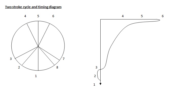
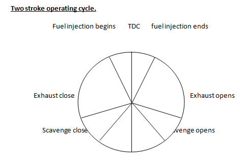
1-2 Completion of scavenge
Air is entering to the cylinder and expelling exhaust gas and recharging it for the next combustion.
Scavenge and exhaust valves open.
2-3 Post Scavenge
Scavenge ports have closed and some air within the cylinder may leak to exhaust.
In some engines 2 – 3 made to coincide to eliminating leakage of air.
3-4 Compression
Exhaust valves has now
closed and the air trapped within the cylinder is compressed by the upstroke of
the piston to raise its temperature sufficiently to ignite the fuel.
4-5-6 Fuel Injection - Combustion
Fuel injection takes palce and combustion occurs causing a rapid rise in pressure.
The period for which the continueos depend upon the fuel pump settings and power to be produced.
6-7 Expansion
Combustion completed, the hot gases expand forcing the piston downwards and convierting the heat energy combustion into work on the piston
7-8 Exhaust Blow Down
Exhaust gas opened allowing to pass to exhaust manifold and pressure drops rapidly in cylinder.
Two stroke cycle
In order to burn the fuel oil sufficient oxygen air must be available in the cylinder at a very high temperature in order to ignite the fuel oil when it is injected into the cylinder. The diesel engine is a compression ignition engine which means that compression of the air charge produces the high temperature for ignition.
Ideal Cycle
These cycles form the basis for reference of the actual perform of IC engine. In the cycles considered in detail all curves are frictionless adiabatic i.e. isentropic. The usual assumptions are made such as constant specific heats, mass of charge unaffected by any injected fuel, etc. and hence the expression “air standard cycle” may be used. There are two main classifications for reciprocating IC
engines.
1. Spark Ignition (SI) – such as petrol and gas engines
2. Compression ignition (CI) – diesel and oil engines
Older form of reference used items such as light and heavy oil engine but this is not very explicit or satisfactory. Four main air standard cycles are first considered followed by a briefconsideration of other such cycles less often considered. The cycles have been sketched using the usual method of P –V diagram.
